Imagine you’re in a new city without any prior knowledge of the streets, landmarks, or directions. To reach a desired destination, you will rely on your phone’s GPS and map app. Now, picture a robot facing a similar challenge—navigating an unfamiliar environment without any human assistance. How does it figure out where it is and how to get to its goal?
This is where a navigation stack comes into play. Just as you depend on maps and real-time directions, robots use software to understand their surroundings, plan paths, and avoid obstacles. In this post, we’ll break down the basics of a navigation stack.
Before diving into the basics of the stack, it’s important to first understand what a robot really is and how does it sense its environment.
What is a robot?
At its core, a robot is a machine controlled by a computer that is used to perform jobs automatically (dictionary, n.d.). Unlike traditional machines, which need direct human control, robots are equipped with sensors, processing units, and actuators that allow them to perceive their environment, make decisions, and execute actions. Whether it’s a vacuum cleaner mapping your living room or a self-driving car navigating a busy city, every robot relies on a set of software and hardware components to interact with the world around it.
Part of the hardware components are the different sensors that allow the robot to perceive the environment to properly function in it. These can be categorized into several types based on the type of data they collect and their functionality. The most commonly used sensors are the following:
Lidar
LiDAR, which stands for Light Detection and Ranging, is a sensing technology that uses lasers to measure distances and create detailed, high-resolution representations of the environment. It works by emitting laser pulses and measuring the time it takes for the pulses to reflect back after hitting objects or surfaces.
Camera
A camera is a vision sensor that captures images of the environment in the form of light. It works by focusing light through a lens onto a sensor that converts the light into digital information. Cameras are used in robotics for tasks like object detection, recognition, and tracking, as well as for creating 2D or 3D maps of surroundings. In stereo vision, multiple cameras can be used to estimate depth and provide a three-dimensional understanding of the environment.
IMU
An Inertial Measurement Unit (IMU) is a sensor that measures a robot’s orientation, velocity, and acceleration. It combines data from accelerometers, which detect linear motion, and gyroscopes, which measure rotational movement. This data helps the robot understand its motion in 3D space, making it essential for tasks like balancing, stabilization, and navigation.
Encoders
Encoders are sensors used to measure the position, rotation, or speed of a robot’s moving parts, such as wheels, motors, or joints. They work by converting mechanical motion into digital signals that can be interpreted by the robot’s control system. There are different types of encoders, such as optical or magnetic, but they all provide feedback about the robot’s movement, which is crucial for precise control and positioning during navigation or manipulation tasks.
For any robot to operate in an environment, it needs to have a map of the area it will operate in. This is where the mapping process comes into play.
Mapping
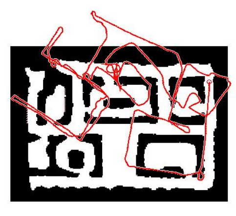
Mapping is a fundamental aspect in the navigation stack that allows a robot to autonomously navigate in an environment. It is achieved when a robot uses its sensors to create a detailed layout of its environment. In the following example, the robot is equipped with LiDAR scanners and it is navigated through the area to explore its different parts.
A challenging aspect in the mapping process is the inaccuracy of its sensors. All sensors are subject to various types of errors, such as noise, drift, and calibration issues. These inaccuracies can accumulate over time, affecting the precision of the map that the robot constructs of its environment. As the robot navigates through its environment, it relies on control commands to estimate its position and orientation. These commands are based on sensor measurements taken at each time step. For example, odometry data might be used to estimate the robot’s movement, while other sensors provide information about obstacles and environmental features.
However, errors in sensor measurements, such as inaccuracies in the rotation or translation data, can lead to distortions in the constructed map. For instance, if there is an error in measuring the robot’s rotation, it can cause the map to become deformed, as the robot’s perceived trajectory will not accurately match its true trajectory. This can result in inconsistencies and inaccuracies in the map.
There exists different techniques and algorithms that address these challenges, allowing the robots to improve the accuracy and reliability of their maps, leading to more effective navigation and interaction with their environments.
One of the common techniques used in robotic mapping is the occupancy grid map. In this method, the environment is divided into a grid of small cells, each representing a specific area of space. Each cell is assigned a probability value indicating whether it is occupied by an obstacle, free, or unknown. As the robot gathers data from its sensors—such as LiDAR, cameras, or sonar—it updates the grid with new information, gradually building a detailed, probabilistic map.
Once a map is available, the robot is now capable of localizing itself in the environment.
Localisation
Localization is the process by which a robot determines its position and orientation within a given environment. Once the robot has a static map of the environment, the robot can then continuously compare its sensor data to this map to update its position.
An efficient method to localize within that map is the Adaptive Monte Carlo Localization (AMCL). AMCL uses a particle filter to estimate the robot’s position on the map. It does this by generating many “particles,” each representing a possible position and orientation of the robot. As the robot moves and gathers more sensor data, these particles are updated, with incorrect guesses discarded and the most likely positions reinforced. Over time, AMCL narrows down the robot’s true position, allowing it to navigate precisely in a known environment while adapting to minor uncertainties or sensor noise.
In dynamic or changing environments, the robot must not only localize itself but also keep updating the map as new obstacles or landmarks appear. One common method to achieve this is through Simultaneous Localization and Mapping (SLAM), which enables the robot to continuously update both its position and the map in real time as it moves through the environment. This allows the robot to adapt to changes and ensure the map stays relevant for future navigation.
Path planning
Once a robot is capable of accurately localizing itself within its environment, it can then proceed to the task of navigation. The core challenge now becomes determining how the robot can autonomously reach a desired end goal. To achieve this, we rely on two essential types of planners: global and local planners.
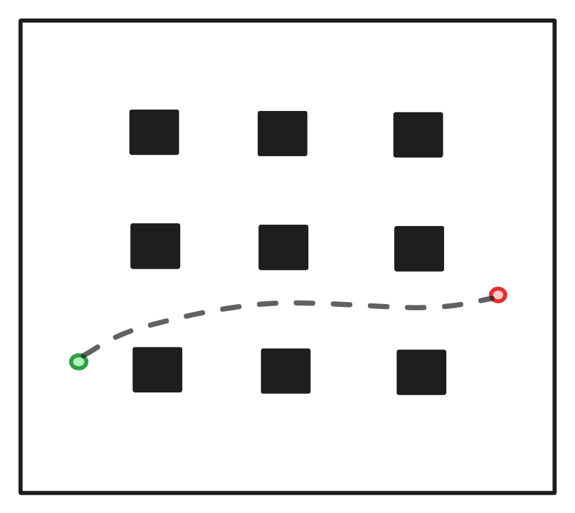
Global planner
Global planners are responsible of generating an optimal path from start to end goal based on the static map of the environment. These path planners rely on a pre-built map and work at a higher level, focusing on the overall route rather than navigating around immediate obstacles. They consider the entire environment, identifying the best path based on factors like distance, time, or safety. An example of a global path planner is the A* algorithm. It finds the shortest path by exploring possible routes in a grid or graph-based map. It uses a combination of cost (distance traveled) and heuristics (estimated distance to the goal) to efficiently find the optimal path.
Global path planners are crucial for robots operating in larger, static environments. They focus on determining the best route from point A to point B while considering known obstacles, and work in combination with local path planners that handle real-time obstacle avoidance.
Local planner
While global path planners create a high-level route from the starting point to the goal, local path planners handle the robot’s real-time, dynamic movements as it follows that global path. Local path planners focus on immediate surroundings, detecting and avoiding obstacles that may not have been accounted for in the global plan—such as people, moving objects, or newly introduced obstacles. These planners ensure that the robot safely and efficiently navigates through its environment while adhering to the overall global plan.
DWA is a popular local path planners, particularly for differential drive robots. It generates possible trajectories based on the robot’s dynamic constraints (speed, acceleration) and selects the one that avoids obstacles and moves the robot closer to the global path.
Global and local path planners work together to ensure efficient and safe navigation. The global path planner gives the robot an overall direction by planning a route through known obstacles and terrain, while the local path planner dynamically adjusts the robot’s immediate movements to deal with unforeseen or moving obstacles.
For example, in a warehouse, the global planner might generate a path from one aisle to another, while the local planner helps the robot avoid boxes or workers that might cross its path during transit.
Conclusion
In this blog post, we outline the basic components needed to operate a robot in an environment. Future blog posts will dive deeper into the different sections for a more detailed overview.